
A vision measuring system — also called a vision measuring machine (VMM), video measuring system, or optical measuring machine — is a non-contact measuring device that uses a camera, a lens, controlled lighting, and a precision moving stage to capture an image of a part and convert it into real-world dimensions. Think of it as a digital ruler that photographs a part, finds its edges automatically, and reports every measurement in millimeters.
A vision measuring system is, at heart, a spatial mapping device: it takes a two-dimensional pixel image and converts it into trustworthy real-world dimensions. That conversion is only as good as three things working together — the optics, the edge detection, and the calibration — and it only holds up in an environment that is stable in temperature and vibration.
Get those right, and a VMM turns the slowest, most operator-dependent job in the quality department into one of the fastest and most repeatable.
If you have ever watched a quality technician measure forty holes on a stamped bracket with calipers, you already understand the problem this machine solves. It is slow, it is tiring, and two technicians will not get exactly the same answer. A vision measuring system does the same job optically, in seconds, without touching the part — and it writes the results into a report you can audit.
What Is a Vision Measuring System?
A vision measuring system is a non-contact optical metrology instrument used for dimensional inspection. The part is placed on a glass worktable, light is shone on it from a controlled source, a camera takes a magnified image, and measurement software locates the edges in that image and calculates real dimensions — lengths, diameters, angles, radii, hole positions, and contours — from them.
Three properties define it:
- Non-contact. Nothing touches the workpiece, so soft, thin, or delicate parts are not deformed by probe force.
- Image-based. Measurement starts from a camera image rather than from a mechanical probe touching a point.
- Software-driven. Edge detection, geometry fitting, tolerance comparison, and reporting all happen in software, which is what makes the result repeatable from operator to operator.
Vision measuring systems are strongest on 2D and 2.5D work: features that live in a plane — profiles, hole patterns, slot widths, pitch, angles — plus height or step measurements when the machine has autofocus. They are widely used in electronics, medical devices, plastic injection molding, stamping, automotive components, and precision machining.
Common beginner confusion: a VMM is not the same thing as machine-vision defect inspection (AOI). AOI answers “is this part good or bad?” A vision measuring system answers “how big is this feature, and is it inside tolerance?” One judges, the other measures.
Also called: VMM, video measuring system, optical measuring machine, image measuring machine
You will see several names for essentially the same class of instrument, and the differences are mostly regional marketing habits rather than technical ones:
| Name | Where you’ll see it |
|---|---|
| Vision measuring system / machine (VMM) | Global, most common in technical writing |
| Vision measurement system | Common in Asia-Pacific supplier catalogs |
| Video measuring system / machine | Older term, from the era of analog video cameras |
| Optical measuring machine | Emphasizes the optics over the camera |
| Image measuring machine | Direct translation from Japanese and Chinese usage |
| 2.5D measuring machine | Emphasizes 2D measurement plus autofocus height |
When you are comparing two quotes, do not assume different names mean different machines. Compare the specifications, not the label.
The 5 Key Parts of a Vision Measuring Machine
A VMM is a system, not a single device. Its accuracy comes from five subsystems cooperating, and a weakness in any one of them limits the whole machine.
| Component | What it does | What beginners should know |
|---|---|---|
| Industrial camera (CMOS/CCD) | Captures the image of the part | More megapixels does not automatically mean more accuracy — optics, lighting, and calibration matter more |
| Lens (telecentric or zoom) | Forms the magnified image | Telecentric optics are the hallmark of metrology-grade vision |
| Lighting (backlight, coaxial, ring, segmented LED) | Creates the contrast that defines an edge | The most underrated variable in the whole machine |
| Precision stage + scales (usually a granite base with linear encoders) | Moves the part and provides coordinates | This is the machine’s reference ruler; temperature drift directly affects results |
| Measurement software | Finds edges, fits geometry, compares to tolerance, reports | Where repeatability and automation actually live |
Why telecentric lenses matter
An ordinary lens magnifies near objects more than far ones. On a measuring machine that is a disaster: two identical holes at slightly different heights would measure as different sizes. A telecentric lens only accepts light rays that travel parallel to the optical axis, so magnification stays constant across its entire depth of field. If a part sits a little high or a little low, the measured size stays correct and only the image sharpness changes. Telecentric lenses also have very low distortion — and what distortion remains is calibrated out on precision machines. The trade-off is physical size: the front element must be at least as wide as the field of view, which makes large telecentric lenses bulky and expensive.
Why lighting is the hidden variable
The same part can produce a crisp, measurable edge or a noisy, unusable one depending entirely on how it is lit. A capable VMM combines several sources under program control:
| Illumination | Position | Best used for | Watch out for |
|---|---|---|---|
| Transmitted backlight | Below the stage | Through-features and outer outlines of opaque parts — produces a crisp silhouette | Opaque parts only |
| Coaxial (through-the-lens) | Down the optical axis | Flat, shiny machined surfaces and holes on a solid part | Glare on rough surfaces |
| Ring light | Around the lens | General top-surface edges | Very low-angle or shallow features |
| Multi-angle / segmented LED | Quadrants around the lens | Stepped, angled, or recessed edges; mixed-surface parts | Needs programming per feature |
| Polarized light | Filter on source and lens | Glossy plastics, painted or transparent parts | Slightly reduces light intensity |
The single most accurate mode is transmitted backlight: an opaque part becomes a black silhouette against a bright field, giving the steepest possible brightness gradient at every edge. When the feature is on a top surface, operators switch to coaxial or ring light. On difficult parts, a program will light only the quadrant that reveals one specific edge while suppressing glare everywhere else.
Treat lighting as part of the measurement program, not as a one-time setup. Changing lighting between batches without reprogramming is one of the most common causes of drifting results in real shops.
How Does a VMM Work? Step by Step
Here is the part that surprises most newcomers: a camera does not capture millimeters. It captures a grid of pixels, and each pixel only records brightness. There is no physical unit anywhere in the image. The machine’s real job is to convert image data into spatial measurements, and that conversion happens in five steps.
Step 1 — Place the part and light it
The part sits on the glass worktable. The operator (or the program) chooses the illumination. For an outline measurement, backlight is used. For a hole on a solid surface, coaxial or ring light.
Step 2 — Capture the image
The camera and lens produce a magnified grayscale image. Nothing has been measured yet — there is only a picture.
Step 3 — Calibrate: build the “digital ruler”
To convert pixels into millimeters, the system is calibrated against a reference artifact — typically a glass calibration plate with known, traceable distances. The software records the relationship between image coordinates and physical coordinates, and in precision systems it also maps and compensates lens distortion and perspective error.
Analogy: calibration is what turns a photograph into a map. Without a scale bar, a photo tells you nothing about distance. With one, every pixel has a defined physical size.
Step 4 — Find the edge, at sub-pixel precision
In a real image, a boundary is not a clean line. It is a gradual grayscale transition several pixels wide caused by diffraction, sensor noise, and surface finish. A VMM therefore does not apply a simple black/white threshold. It analyzes the grayscale gradient and locates the most stable boundary position within that transition — often resolving it to a fraction of a pixel (sub-pixel edge detection).
This is why a well-lit, high-contrast edge can be located extremely precisely, while a soft or shadowed edge defeats even the best camera. The math cannot invent contrast that the lighting did not create.
Step 5 — Fit geometry and report
Edge points are fitted to geometric elements — points, lines, circles, arcs — and the software calculates the dimensions you asked for: distances, diameters, angles, radii, position. It compares each result against the drawing tolerance, flags pass/fail, and exports a report with numeric data, images, and overlays. On CNC machines this whole sequence runs unattended, feature after feature.
Three things ultimately determine whether the number is trustworthy: the optical imaging system, the edge detection method, and the calibration model. When any of the three is unstable, results drift — even if the procedure looks identical.
What Can a VMM Measure?
Basic features: points, lines, circles and arcs, angles, distances, radii, slot widths, hole diameters and hole-to-hole positions, contours and profiles.
Geometric tolerances (2D): position, concentricity, circularity/roundness, profile of a line, parallelism and perpendicularity within the measuring plane.
2.5D features: with autofocus, the Z axis can measure height differences, step heights, and flatness across a surface. Some machines stitch multiple focused images into a single extended-depth-of-field image.
Where it stops: a camera can only measure what it can see. Deep internal bores, undercuts, enclosed cavities, hidden datums, and true 3D free-form surfaces belong to a tactile CMM or a multi-sensor machine with a touch probe or laser sensor.
Types of Vision Measuring Machines
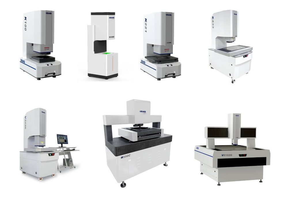
| Type | How it’s operated | Typical travel (X–Y) | Best for |
|---|---|---|---|
| Manual / semi-automatic benchtop | Operator drives the stage by hand or joystick | 100–250 mm | Low-volume inspection, first-article qualification, rework checks, toolroom |
| CNC vision measuring system | Programmed routine runs autonomously | 200–600 mm | Repeat production inspection, metrology labs, tight-tolerance batch work |
| Instant / “flash” measurement | Place part, press one button | 100–200 mm field of view | High-volume shop-floor go/no-go, hundreds of identical parts |
| Multi-sensor (vision + touch probe + laser) | Full CNC, multiple sensors sharing one coordinate system | 200–650 mm | Parts needing both optical speed and 3D reach — deep bores, undercuts, surface profile |
| Large-format gantry | Full CNC bridge frame | 600 mm and up | PCB panels, glass, sheet metal, large stampings |
Names you will encounter: Mitutoyo Quick Vision, Zeiss O-INSPECT, Hexagon OPTIV, OGP SmartScope, Nikon NEXIV, Werth ScopeCheck, and Keyence IM / LM series. The first group represents lab-grade CNC and multi-sensor platforms; the Keyence-style machines pioneered the one-button production category, where an operator with no metrology training can place a part, press a button, and get a full report in seconds.
VMM in Action: 3 Real Examples
Example 1 — Electronics connector: pin pitch and coplanarity
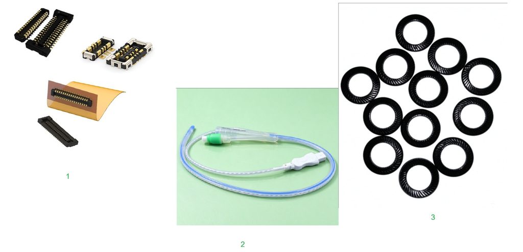
The part: a fine-pitch connector with dozens of stamped pins.
What is measured: pin pitch (spacing), pin width, tip position, and coplanarity of the pin tips.
Why a VMM: the pins are thin and springy. A contact probe pushes them aside and the reading is wrong. There are also far too many features to measure by hand — a program can step through every pin in one cycle and report all of them, so a single setup replaces dozens of manual measurements. If pins are bent, missing, or out of plane, the part will not solder reliably on the PCB.
Example 2 — Medical catheter or silicone seal: inner diameter and wall thickness
The part: an extruded catheter tube or a molded silicone seal.
What is measured: inner and outer diameter, wall thickness, and profile conformance.
Why a VMM: the material is soft. Any contact force compresses it, and the measured dimension becomes a function of how hard you pressed. Non-contact optical measurement removes that variable entirely. This is not academic — lumen diameter controls drug dosage in a catheter, and seal geometry controls whether an IV connection leaks. Medical device manufacturing also operates under documented quality systems that require traceable, repeatable records, which VMM software produces automatically.
Example 3 — Stamped gasket: profile versus CAD
The part: a flat stamped gasket or washer with a complex outline.
What is measured: the complete 2D profile, compared against the CAD model; hole positions and slot widths.
Why a VMM: the old method was a profile projector — project the silhouette onto a glass screen and compare it against a drawn overlay by eye. It works, but it depends on operator judgement and produces no data. A VMM measures the same silhouette in seconds, overlays it on the CAD file, reports deviation at every point, and stores the result. Because gaskets and seals are flat, thin, and flexible, they are close to the ideal VMM workload.
A fourth quick one: injection-molded plastic housings — warpage, shrinkage, boss positions, and gate vestige — measured in bulk to catch mold wear before it produces scrap.
VMM vs. Calipers, Optical Comparators, and CMMs
New buyers often frame this as “which one is better.” It is not a contest — the four tools sit at different points on a speed-versus-capability curve.
| Calipers / micrometers | Optical comparator (profile projector) | VMM | CMM | |
|---|---|---|---|---|
| Contact | Contact | Non-contact | Non-contact | Contact (or multi-sensor) |
| Speed | Slow, one feature at a time | Medium | Fast — seconds for dozens of features | Slow — minutes |
| Data output | Manual recording | Mostly visual | Full digital data, SPC, overlays | Full digital data, GD&T |
| Typical accuracy | ~10–25 µm, operator-dependent | ~5–10 µm | Commonly 1.5–3 µm plus a length term | Very high for 3D volumetric work |
| Best at | Quick single checks on the bench | 2D silhouette comparison | 2D/2.5D features on small, thin, soft, or high-feature-count parts | 3D geometry, datums, deep bores, free-form surfaces |
| Worst at | High feature counts, soft parts | Anything needing numbers or 3D | Hidden features, true 3D form | Delicate parts, high-throughput 2D |
The practical answer: many factories run both. The vision measuring system screens production quickly and catches the outliers; the CMM is then used to deeply analyze the failures. Multi-sensor machines exist precisely to avoid measuring the same part twice — every sensor reads against one coordinate system in a single fixturing, eliminating the re-fixturing error you get from moving a part between two machines.
How to Read a VMM’s Accuracy Spec
This is where most first-time buyers get misled, and it is worth slowing down.
Accuracy is a formula, not a number
A credible VMM spec is written as E = a + L/K (µm), where L is the measured length in millimeters. For example, a machine might be specified at (1.5 + 5L/1000) µm. The fixed term (1.5 µm) is the floor error near zero length, set by edge detection, scale resolution, and optics. The proportional term grows with distance: at L = 200 mm it adds 1.0 µm, at L = 400 mm it adds 2.0 µm.
Because of the length term, an accuracy figure is meaningless unless you also state the length it applies to. Always compare two quotes at the same length, on the same axis designation (one axis versus the whole plane), and at the same reference temperature.
Look for ISO 10360-7
Vision measuring machines are coordinate measuring machines, and their acceptance testing falls under the ISO 10360 family. The part that governs imaging systems is ISO 10360-7, which defines acceptance and reverification tests and how a manufacturer declares a Maximum Permissible Error (MPE). Laser and confocal point sensors are covered separately by ISO 10360-8.
Beyond the length-measurement error, two more declared values fill out the picture:
- PF2D (probing/form error) — how repeatably the imaging system locates a single feature, the optical equivalent of a tactile probe’s form error.
- Repeatability — the scatter of repeated measurements of the same feature under identical conditions.
A single-point repeatability number quoted on its own is a marketing number. Ask for the full ISO 10360-7 acceptance report when your tolerance budget is tight.
Three traps that catch beginners
- Believing the headline number. Spec-sheet accuracy is measured under laboratory conditions. In metrology, temperature matters more than almost anywhere else: ISO 10360 figures are stated at 20 °C, and glass scales and granite bases expand when they warm up. Precision installations hold ±1 °C with a gradient under 1 °C per hour and per meter, and put the machine on vibration isolation. A machine that meets sub-micron specs in a controlled room can drift well outside them on an uncontrolled shop floor.
- Setting lighting once and forgetting it. Lighting belongs in the measurement program, alongside stage motion and edge-detection settings. Reprogram it when you change part or batch.
- Ignoring fixturing and cleanliness. Dust, fingerprints on the glass, and a part that is not lying flat all move the edge — and therefore the number.
Advantages and Limitations
Glossary
| Term | Plain-English meaning |
|---|---|
| FOV (field of view) | How much of the part the camera sees in one image |
| Telecentric | A lens design where magnification does not change with part height — essential for accurate measurement |
| Sub-pixel | Locating an edge to finer precision than one camera pixel |
| MPE | Maximum Permissible Error — the declared accuracy limit under ISO 10360 |
| ISO 10360-7 | The standard governing acceptance testing of vision-equipped measuring machines |
| 2.5D | 2D measurement plus height measurement via autofocus — not true 3D |
| Multi-sensor | One machine combining a camera with a touch probe and/or laser sensor |
Advantages
- Non-contact — no probe force, no deformation, no wear on the sensor
- Fast — dozens of features in seconds, especially on CNC and instant-measurement machines
- Repeatable — the software makes the same decision every time, independent of operator skill or fatigue
- Digital by default — data, images, overlays, SPC, and traceable records come out automatically
- Gentle on delicate parts — ideal for thin, soft, flexible, or easily scratched components
Limitations
- It can only measure what the camera can see — no hidden features, deep bores, or undercuts
- Transparent, highly reflective, and low-contrast parts need careful lighting and sometimes special sensors
- True 3D volumetric GD&T is the domain of a CMM or multi-sensor machine
- Accuracy depends on environment: temperature stability, vibration, and cleanliness
- Large telecentric optics are expensive, which is why large fields of view cost disproportionately more
Is a VMM Right for You? A 5-Question Checklist
Answer yes to most of these and a vision measuring system is probably your right first metrology investment:
- Is the part flat, small, thin, or easily deformed? Non-contact measurement pays off immediately.
- Are the critical dimensions mostly planar features — holes, slots, profiles, angles, positions?
- Does one part have more than about ten features to check? Manual measurement becomes the bottleneck long before that.
- Is your daily inspection volume high enough that speed matters? If you check hundreds of parts a day, seconds per part compound quickly.
- Are your tolerances in the micron range but not requiring true 3D datums? If you need volumetric GD&T, go straight to a CMM or multi-sensor platform.
A sensible growth path: start with a 2D/2.5D vision measuring system for vision-dominant work, keep a CMM or an outside service for contact-only features, and move to a multi-sensor machine only when inspection volume justifies consolidating both into one cycle.
FAQ
What is a vision measuring system used for?
It is used for non-contact dimensional inspection — measuring lengths, diameters, angles, hole positions, and contours on parts that are small, thin, soft, or feature-dense. Typical users are electronics, medical device, plastics, stamping, and precision machining manufacturers.
What’s the difference between a VMM and a CMM?
A VMM measures optically and without contact, excels at 2D/2.5D features, and is fast. A CMM touches the part with a probe, excels at true 3D geometry and volumetric tolerances, and is slower. They are complementary, and multi-sensor machines combine both in one frame.
How accurate is a vision measuring machine?
Reputable machines quote accuracy per ISO 10360-7 as a formula, typically around 1.5–3 µm plus a length-dependent term, measured at 20 °C under controlled conditions. Real shop-floor results will be wider than the lab figure.
Is a vision measuring system the same as an optical measuring machine?
In practice, yes. The two terms are used interchangeably, along with video measuring system and image measuring machine. Compare specifications rather than names.
How much does a VMM cost?
It depends heavily on travel, optics, automation, and sensors. Entry-level manual benchtop machines are a few thousand to a few tens of thousands of US dollars; mid-range CNC systems run into the tens of thousands; large-format or multi-sensor platforms can reach well beyond that. Budget for calibration, training, and environmental control as well as the machine.
Do VMMs need to be calibrated?
Yes. Calibration establishes the pixel-to-millimeter mapping. Beyond periodic formal calibration, daily checks against a reference artifact are standard practice in any shop using the machine for documented inspection work.